The Kinetics of Polymerase Chain Reaction Product Duplex Dissociation
Link to Full Thesis Python Git Repository
BACKGROUND:
Polymerase Chain Reaction (PCR) is a biochemical reaction that amplifies DNA and is the cornerstone of modern molecular biology. A typical PCR reaction has three components: denaturation, annealing and extension. To optimize this reaction one must tinker with each of these steps to achieve maximum efficiency. Two of the reaction steps, extension and annealing, have been extensively studied. The speed of the denaturation reaction has been largely overlooked due to the technical limits of current instrumentation. With the goal of advancing PCR technology, I sought to increase the precision with which one can measure the speed of DNA denaturation.
How do you systematically study DNA denaturation?
The overall goal of the project was to see how fast DNA denatures (i.e. goes from a double to single stranded molecule) given an "insult" to the system. This insult can be anything that changes the thermodynamic stability of DNA such as: heat, pH or chemical denaturants. I wanted to develop a method to record how fast DNA responds to changes in solution conditions. In a theoretical system, the insult would be instantaneous, however, experimentally this is difficult to achieve. To this end, I tried numerous methods of measurement, a subset of which are depicted below.
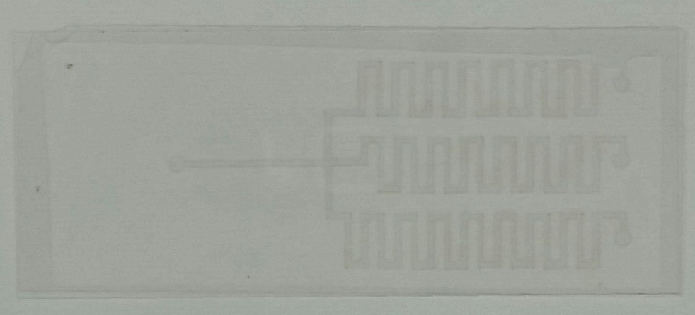
Microfluidic mixing

Early attempt to study DNA denaturation
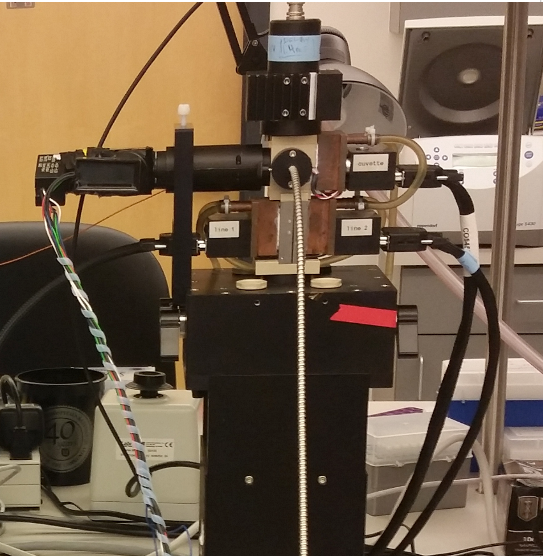
I discovered that the most reproducible and systematic method was to use a stopped-flow instrument. This instrument mixes two solutions at different temperatures together. When the two lines are mixed, the solution temperature "jumps." The reaction is then observed in the downstream cuvette. An overview of the stopped-flow instrument is shown below.

With the use of a stopped-flow instrument, precisely controlled temperature jumps can be performed. The difference in temperatures between the lines determines the resultant temperature jump. Varying the temperature of the input line can produce temperature jumps of vastly different magnitudes.
I am interested in studying the kinetic rate conversion of fully duplexed (double stranded) to single stranded DNA. What should the temperature be of each input line and the mixed solution? The melting temperature, or Tm, of DNA is the temperature at which there is a 50% concentration of duplexed DNA in solution. The temperature of the DNA solution needs to "jump" over the Tm.
The figure below depicts the derivative melting curve, where the peak corresponds to the Tm, showing the temperature jumps performed for a particular PCR product. The input line containing the DNA is kept below the Tm. The temperature of the second line is varied to produce temperature jumps. The equilibrium temperatures (i.e. the result of the mixture of the hot and cold input lines) are shown to the right of the arrows.
PROBLEM 1: Temperature Control
The above figure underscores the need for precise temeprature control. The major challenge was overcoming the shortcomings of the instrument's temperature monitoring. The factory system is diagramed below. A thermocouple is embedded into an assembly and placed against the face of the cuvette.

My major breakthrough was the realization that a thermocouple could be threaded through the instrument to measure fluid temperature.

At low temperatures, the divergence between real fluid temperature and reported temperature was negligible. As the temperature of the cuvette increased, toward more realistic PCR reaction conditions, the divergence was greater than 5 °C. The experiments required temperature accuracy of tenths of degrees Celsius, making this 5 degree difference unacceptable.

PROBLEM 2: DNA duplex indicator dyes are temperature dependent
When using a DNA indicator dye, the intensity of fluorescence in the solution is dependent on 1) concentration of duplex DNA and 2) the temperature of the solution. The following GIF shows the affect of a stopped-flow temeprature jump.

The loss of fluorescence could be the result of a temperature change within the cuvette (false-positive result), or denaturation (positive result).
In stopped-flow temperature-jump experiments, a major optimization step is ensuring that the cuvette temperature is the same temperature as the incoming fluid. Any difference in temperature hinders one's ability to attribute the fluorescence change to DNA denaturation. As a result, I sought to understand how one can accurately monitor temperature without direct access to the solution.
SOLUTION: Temperature indicator dye
The fluorescent dye Sulforhodamine B was used to accurately measure solution temperature as a function of its fluorescence. Before each experiment, the indicator dye's florescence emission was calibrated as a function of cuvette solution temperature. This involved partially dissembling the instrument and placing a thermocouple directly in the cuvette. As the temperature of the cuvette was increased, the emission fluorescence decreases.

After calibration, the thermocouple is removed and the instrument re-assembled. The sulforhodamine B emission can be used to accurately measure temperature using first-order rate equations. Using an indicator dye, the instrument can be used in a standard operating configuration while the internal fluid temperature can be externally monitored.

The stopped-flow instrument in the two configurations illustrated above are shown below. Temperature calibration (right) and kinetic study (left).


PROBLEM: Optics and data collection
To accomplish my goals, this system needs to be able to excite and record two dyes. One dye measures the DNA duplex concentration (intercalating dye) and a second indicates the temperature of the system. Once the indicator dye is calibrated, the optical system must not be moved. Any subtle variation will drastically reduce the accuracy of the fluorescent temperature measurements. The system also needs to be able to provide real-time scaled temperature information from the Sulforhodamine B dye fluorescence. The factory supplied software/hardware cannot accommodate these parameters. Two separate systems (optical and stopped-flow) need to be used in conjunction to study denaturation. My custom system records the fluorescence in LabVIEW and a second factory-standard system controls and regulates the instrument.

SOLUTION 1: OPTICAL HARDWARE
The stopped-flow cuvette assembly determined the optical instrumentation. The assembly is essentially an aluminum cage with four ports that heats and cools the cuvette (above). Two sides of the cuvette are utilized by the regulation thermocouple and peltier. This leaves two ports to place the excitation and emission optics. To get two independent emission intensities out of one cuvette face, the emission light is split using a dichroic mirror into two photomultiplier tubes (PMT), one for each channel (DNA and temperature indicator dye).

The excitation sources for each dye are combined using a second dichroic mirror and focuessed into a fiber bundle.


